• Darwin Motion +61 432112288    Darwin Motion +91 8956113099
  • Blogs
  • FAQ's
  • Testimonials
Logo
  • Home
  • About Us
  • Team
  • Data Sheets
  • Products
      Products
      • Micro Drive
        • Matrix-900

      • DR Matrix 350 / Solar Drive
        • Matrix 350 Products
      • HIGH FREQUENCY DRIVE - HF
        • DR Matrix 500

      • High Performance Drive
        • DR Matrix 680

      • Regenerative Drive
        • DR Matrix 880
  • Applications
      Applications
      • Engine & Motor Testing Dynamometer

      • Textile Machine
        • Textile Dying Machine

      • Winding Industry

      • VFD for Bar Mill
      • Extrusion Machine Haul-off Application

      • VFD for injection molding Machine

      • Spinning Machine Application

      • Multiple Pump VFD
      • Winding Industry
      • Extruders
      • Cross Cutter Metal Cutting
      • High Speed CNC Spindal Drive
      • TFO Machine Application
      • Tower Crane
      • Wire Drawing Machine
      • Flying Sheer

      Why Us?

      Our team of Designing Engineers has extensive experience spanning several decades in the research and development of automation technology.

  • AC Drives
      AC Drives
    • Active Front End VFD
    • Bi-directional Power Supply
    • VFD
    • Variable Frequency Drive
    • Servo Drive
    • High Frequency Drive
    • Profinet Communication Drive
    • EtherCAT Communication Drive
  • Certificates
      Certificates:
    • CE UKCERT EMC
    • ROHS UKCERT
    • ISO 9001
  • catalogue
  • contact

Flying Shear Applications

  • Home
  • Applications
  • Flying Shear Applications
  • Overview
  • Introduction
  • Key Advantages
  • Applications
  • Characteristics

Introduction

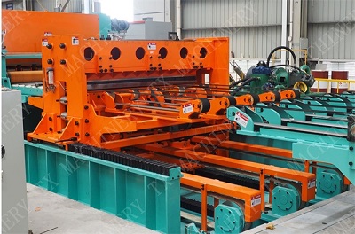
Flying-shear applications typically involve cutting a moving web of material into predetermined lengths on-the-fly, without stopping the movement of the material web. Although flying shear maximizes productivity, since the material doesn’t slow down or stop during the cutting process, it can be a particularly challenging application to achieve because the cutting tool must be precisely synchronized with the material web — otherwise, the cut may take place at the wrong position or be incomplete, leading to material scrap and downtime.

Key Advantages

  • Acceleration: The shear accelerates to match speed of material web.
  • Synchronization: When the shear speed exactly matches the speed of the material web, the shear switches to constant velocity and maintains that speed while the cutting operating is performed. The synchronization phase can be further broken down into settling time, cutting time, and rise time, based on the movements of the tool.
  • Deceleration: Once the cut is complete, the shear rapidly decelerates in order to minimize the amount of material movement that takes place during this phase.
  • Repositioning: The shear moves back to the initial position so it can repeat the cycle for the next cut.

Flying Shear Applications:

  • Flying-shear applications usually include cutting material moving web into fixed lengths on-the-fly, without stopping the material web movement. Though flying shear increases productivity, as the material doesn’t stop or slow down during the cutting procedure, it can be mainly perplexing application to attain as the cutting tool must be exactly synchronized with the web of the material — or else, the cut might take place at the incorrect position or be inadequate that leads to material scrap and downtime.
  • Flying shear applications are often defined in four phases based on the consideration of reference/follower system type wherein the follower motion axis is defined by the reference axis motion:
  • Acceleration: Acceleration of shear take place to match web material speed.
  • Synchronization: The shear gets back to constant velocity and maintain the same speed while the cutting operation is performed, when the speed of shear accurately matches the material web speed. The phase of synchronization can be more broken down into settling time, cutting time, and rise time depending on the tools movement.
  • Deceleration: After completion of cut, the shear quickly decelerates for minimizing the material movement range taking place during this phase.
  • Repositioning: The shear goes back to the previous position so it can replicate the cycle for the subsequent cut.
  • The reference and follower axes synchronization is often done through an electronic cam connecting the shear movement to the material web movement. The material web can be run in an open-loop system; however, an encoder need on this axis for communicating its position to the controller. Instead, the shear is run in a closed-loop system, with its movement determined by web feed position together with the cam profile that is programmed inside the motion controller. When the web and shear are synchronized and the shear remain in the right position, the cutting tool become activated.
  • Flying shear are parted into two subtypes i.e. parallel wherein the cutting tool makes a movement parallel to the material flow, and second angled, wherein the cutting tool makes a movement at an angle to the material flow.
  • Parallel flying shear is utilized when the whole cut is performed at once, since with a blade or punching tool that extents the material width to be cut.
  • Saws or plasma cutters tools have to move across the material for making a cut. In these conditions, if the tool were to just cut direct across the material with the web movement, the output cut would be at an angle. However, the goal is usually achieving a cut straight across the material that means the cutting tool have to make a movement at an angle to the material flow. The tool motion angle and speed together with material web speed, decide the exactly angle at which the cut will be made. For a specified web speed, the higher the angle of the motion of tool, the quicker the tool will need to navigate across the web for achieving a 90° cut, direct across the material web.

Characteristics

  • Darwin Motion Matrix Drive provide a fast and accurate response to changes in load or speed, which is important in flying shear applications where the cutting blades need to be precisely controlled.
  • Darwin Motion VFDs have the ability to handle temporary overloads, which is useful in flying shear applications where the cutting blades may encounter unexpected resistance or material.
  • Celebration and deceleration of the cutting blades to be adjustable, which helps to minimize wear and tear on the blades and machine components.
  • Can detect faults in the system and protect against overloads, overvoltage, undervoltage, and other issues that could damage the machine or its components.
  • Also Drivecan reduce energy consumption by controlling the speed of the cutting blades, which helps to reduce waste and lower operating costs.
protocols
protocols
protocols
protocols
protocols
protocols
protocols
protocols
protocols
protocols

About

  • Darwin Motion

    Email : sales@darwinmotion.com

  • Darwin Motion

    Darwin Motion, Office No - 212 Xion Pacific , Hinjewadi Pune Maharashtra India 411057

  • Darwin Motion

    Darwin Motion, Suite 379 Level 2/66 Victor Crescent NARRE WARREN VIC 3805

AC Drives

  • Micro Drive- Matrix 900
  • DR Matrix 350 / Solar Drive
  • DR Matrix 500
  • DR Matrix 680
  • DR Matrix 880

Blogs

  • VFD
  • Servo Drive
  • High Frequency Drives
  • Profinet Comunication Drives
  • EtherCAT Communication Drives

Quick Enquiry

Call Us Today

Darwin Motion +91 8956113099
Darwin Motion +61 432112288

Opening Hours

  • Mon - Sat :
    10.00 am - 7.00 pm
  • Sun :
    Closed

Factory Address:

    Darwin Motion Gat no 309,ne bapdev mandir nighoje, Chakhan, Pune, Maharashtra 410501

© Copyright 2019. All Rights Reserved by Darwin Motion

  • Terms of use
  • Privacy & Policy
  • FAQ's
  • Blogs
  • Darwin Motion Matrix VFDs